
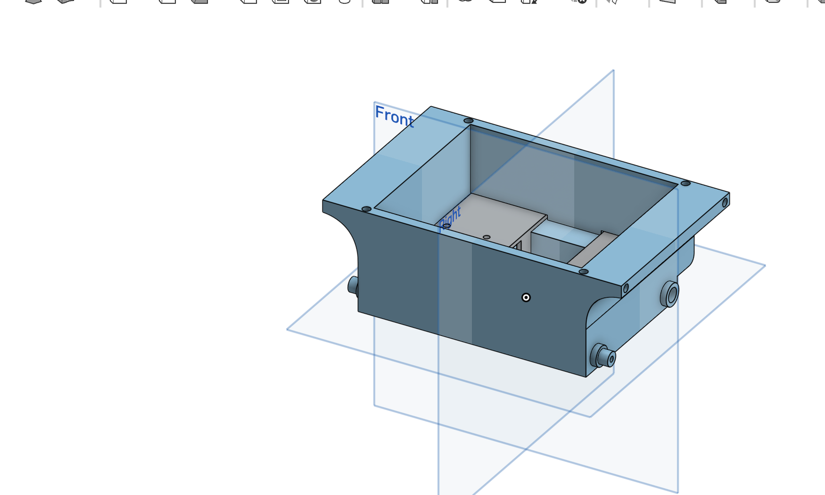
The chassis print is the robot's frame. The current CAD places the two motors inside it and the wheels through the side openings. Install the motors before the deck goes on.
First-build note: This assembly sequence follows the CAD but has not yet been checked against a complete physical build. Test-fit every printed part and fastener before installing inserts or tightening hardware. Stop if a part needs force or the holes do not line up.
1. Fit the drive motors
Test-fit one N20 motor in each matching recess, with its output shaft through the side opening. The two motor covers are mirrored; try each cover and keep the pairing that sits flush with its mounting holes. Once the fit is clear, secure the covers with the matching M3 hardware. Install an insert only where a screw is meant to thread into the print.
Before moving on, tug each motor's leads gently. Both pairs need to reach the NoU3 while the deck is still off.
2. Press on the wheels
Check that the wheel hub matches the motor shaft, then press the wheel on using the wheel supplier's intended orientation. Do not assume the bore is a particular shape, and do not force a hub that does not start with light pressure. Spin each wheel by hand. You will feel the gearbox's resistance, but the wheel should not wobble on the shaft.
3. Assemble the idle wheel
The CAD shows the printed idle wheel and its holder as separate pieces. Test-fit the wheel in the holder and choose the M3 fastener that lets it spin without side-to-side slop. Match the holder to the mounting holes shown in the CAD assembly, then secure it without clamping the roller. This wheel is not driven; it only supports the chassis.
4. Roll test
Push the chassis across a table. It should roll with all three wheels touching. If the idle wheel drags, check the roller's axle clearance and fastener stack before changing the holder's mounting screws.
Keep the deck off. Build the arm on the detached deck next, then wire and test the electronics before closing the chassis.