
All of the starter bot's structure is 3D printed. Open the Starter bot CAD document on Onshape in your browser. A free Onshape account lets you copy and export it.
What to print
Print the eight structural parts listed below. They live in the Part Studio tabs along the bottom of the Onshape window:
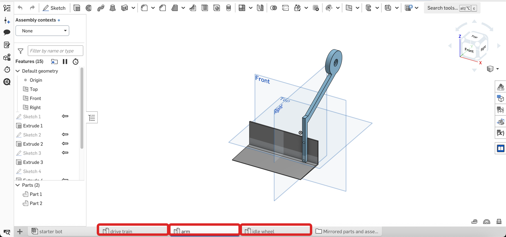
| Part | Qty | Found in tab |
|---|---|---|
| Drive chassis | 1 | drive train |
| Cover (top deck + servo tower) | 1 | drive train |
| Motor cover, left | 1 | drive train |
| Motor cover, right | 1 | drive train |
| Arm linkage | 1 | arm |
| Scoop | 1 | arm |
| Idle wheel | 1 | idle wheel |
| Idle wheel holder | 1 | idle wheel |
Don't print the wheels or components that look like a motor, servo, or servo horn. The rubber-tired wheels and N20 motors are store-bought parts, and the star-shaped horn comes with the MG996R servo. They appear in the CAD to show fit and assembly.
Export from Onshape
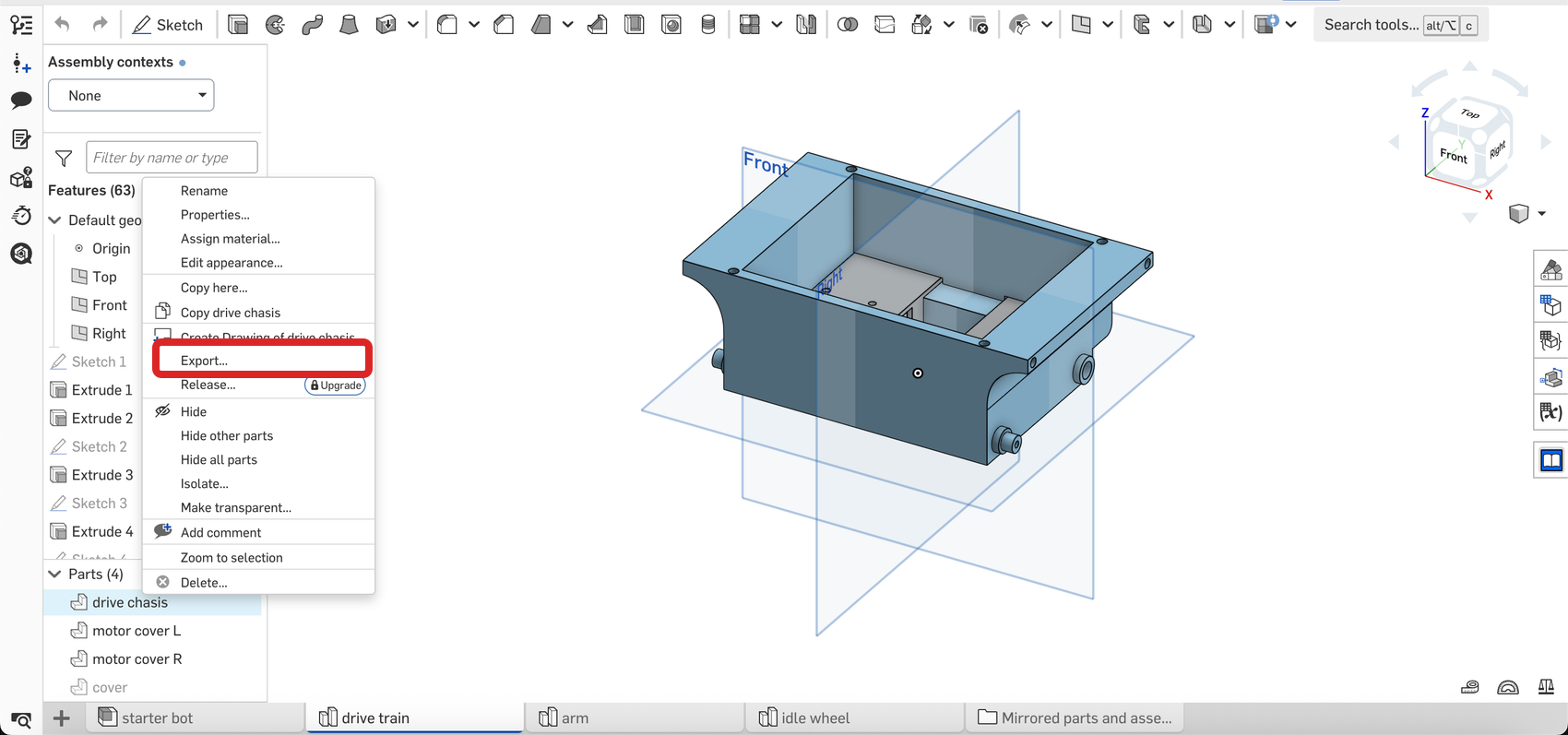
- Open a part studio tab (start with drive train).
- In the parts list at the bottom left, right-click a part and choose Export…
- Pick 3MF (or STL if your slicer prefers it) and download.
- Repeat for the other seven parts in the table. All eight printed parts export from Part Studio tabs; you do not need to export anything from the starter bot assembly.
Print settings
Use these PLA settings as a starting point. Orientation and support needs have not been verified for every part, especially the chassis and cover/tower:
- 0.2 mm layers
- 3 walls, 15–25% infill
- Start by placing the largest flat face on the build plate
Check the slicer preview before committing the big prints: if a part shows steep overhangs in the orientation you chose, re-orient it or add supports. Start the chassis first because it is the biggest print. Queue the smaller parts after it, or run them at the same time if another printer is available.
Test-fit before installing inserts
Do not put an insert in every opening ahead of time. The exact fastener locations have not yet been checked against a complete physical build, and a through-hole or pivot must stay clear.
Identify each joint during assembly. If an M3 bolt is meant to pass through and turn in the opening, leave it bare. If a screw is meant to thread into a printed part, test-fit the insert first, then press it in level with a hot soldering iron and let it cool. When the intended fastener is not clear, stop and compare the joint with the CAD assembly instead of forcing it.
When every part is off the bed and cleaned up, head to the drivetrain with the inserts still set aside.